|
Board cont'd
As I mentioned before, the memory slots are coloured green and purple which serve as an indication for installing ram in a Dual Channel configuration, one of the big selling points of nForce2 chipset motherboards. Some may find it confusing in that one would think that putting 2 sticks into the purple slots, and therefore keeping the colours the same would give you a Dual Channel configuration. This isn't the case however, as is explained in the manual you will need one in a purple slot and one in the green slot. I guess it all depends on how you think. I don't personally feel that anyone has come up with a satisfactory way of visually indicating this feature at a glance as yet.

|

|
In between the memory slots and the IDE connectors we find the southbridge or MCP-T chip just left of the battery and Clear CMOS jumper. This chip which supplies support for dual LAN, Firewire, up to 6 ports of USB 2.0 as well as ATA133 IDE, is covered with a green sticker showing off the fact that this board has official support for 400 FSB.

|

|
Moving down we find the 3 IDE connectors (just under the battery and Clear CMOS jumper), one of which is reserved for RAID as supplied by the Promise PDC20376 controller. This controller also gives us support for the 2 SATA headers, and it's possible to RAID both the SATA ports or one SATA and the Promise supplied IDE port. SATA hasn't as yet become mainstream but things are moving in that direction so inclusion of these two headers will help to future proof (if such a thing is possible) your motherboard somewhat. Having the IDE and SATA headers this low down is a great position as chances are this is where your Hard Drives are going to be found, in the lower half of your system. The floppy header is higher up on the board and should hopefully provide a bit of extra length in reaching the floppy drive in those systems that have it at the top rather than the bottom. Users of cases without removable motherboard trays might have a bit of a difficult time with the HDD LED header and its brethren, since they are right down at the bottom of the board, and just under IDE 1. This means you'll need to install those before putting in the IDE leads.

|

|
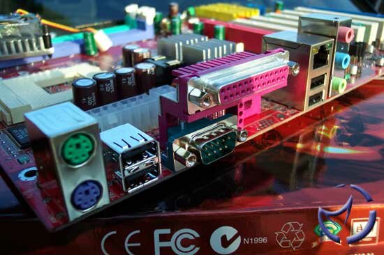
The back I/O panel has all the features that have become common nowadays. Starting from the left we have the 2 P/S2 ports for keyboard and mouse, followed by 2 of the USB 2.0 ports. Next are the Parallel and Serial ports, one of each although there is room for a second serial port. Not a big annoyance since the use of serial ports has dropped a lot in this age of USB. Next up are the LAN and 2 more USB ports, again of the USB 2.0 standard. And finally we find the sound jacks, as controlled by the Realtek ALC650 6-channel audio.
All in all, the board layout isn't bad apart from the power connectors, and overall looks fully featured (as it is) but not overly cramped.
Previous Page - Technology
Next Page - Bios and Overclocking
|
 MSI K7N2 Delta-ILSR: Whilst the original nForce2 supports DDR400, it doesn't officially support 400 FSB and as we have come to learn, the best performance can be found when running your FSB and memory synchronously. This is where the nForce 2 Ultra 400 steps in.