
In the past, nobody really cared about the exterior of a PC, much less the interior. I was once content with my beige medium tower, and didn't bother taking an air gun to clean up the dust bunnies inside. This has changed over the years, and now looks are pretty much a big part of the buying decision. At the same time, a clean interior, other than looking nice, has an additional benefit of keeping ambient temperatures lower. is a prime example of interior cabling done right.
I'm sure most of you are pretty good with cabling. With the popularity of case windows and such, it'd be kinda embarrassing to to show off your interior if all you had to show was a months worth of dust on your heatsinks and fans, and an assload of cables and wires hanging all over the place. In order to reduce clutter, many enthusiasts have taken to rounding their cables. This has become such a popular concept, that many companies started to sell machine rounded IDE cables. It's been argued that these cables are useless, and to an extent, I'd agree. If you're neat, round cables won't help your PC run any cooler, nor help it run any faster. At the same time, they do look prettier than sliced up grey IDE cables with zip ties around them.
Though a few things are common sense to most users, I thought it'd be nice to show a few step-by-step pictures of what I've done when recently upgrading my PC. This guide is geared more towards novices, directing those who have either not taken the time to tidy up the interior, or those who weren't sure where to start. Maybe some more experienced readers may learn a thing or two. Although I'll use a rounded IDE cable or two, you don't need to spend a lot of money to do this. The point is to clean things up, for let's say, ...10$, and not using much more than scissors and a screwdriver. This guide isn't perfect, as the case I've chosen for this project makes things a bit challenging. Hopefully, this will give you a few ideas, and if you have any suggestions, feel free to let us know.
I'm using the Antec SX1030B for this guide. What makes this case particularly difficult to work with is the fact that it's huge. Not overly large mind you, but making cables stretch won't be too easy. I won't be using oversized cables or modified power supply connections. You'll see what I mean as we go on. Part two of this series will be with the much smaller Lian-Li PC60, which will present different challenges.
Those Grey Cables....

IDE and floppy cables can be tough to work with, especially with the secondary drive connections in the middle. If you practice good IDE cabling, you'll know that ideally, you'd want any IDE drive to be the not only the master, but also be alone on the IDE channel. This will be the optimal operating conditions. 18" cables are typical, and if I remember correctly, are the recommended length according to ATA/66 specifications. Any longer, and there is a possibility of data corruption.

So what can we do about flat IDE cables, without resorting (read: spend money) to round cables? Fold them of course. I'm well aware you can make round IDE cables manually, but it won't work with the trick I'm going to show you. Folding cables is easy enough, and in most cases, it should hold it's shape well. Just be careful not to over do it, since if you ever decide to take it apart, you're going to have a tough time working all those wrinkles out. Throwing it into your dryer with a "Bounce" sheet isn't suggested.
If you're still using a floppy drive, which isn't always necessary since CDROMs can be set as bootable, you'll know that the 5 1/4" conections (or whatever those are) are still there. "Why?" is beyond me. Now, you could pop these off with an exacto knife, but because these are clamped in with "teeth", I'm not sure if the exposed wiring will cause instability.

In my case, my motherboard, the Abit KG7-RAID, can cause some problems since the RAID and floppy connections are on the bottom of the motherboard. This makes hiding the cables a bit tougher, if you simply want to fold them. I considered round IDE cables here, but on the Antec case, the hard drive bay is awfully close to the RAID controller, and I figured it'd just look cluttered. So what was my solution? Fold the cables, but fold them under the motherboard. I'd like to say that I came up with this idea by myself (which I did), but I recently read at that they had the same idea. Oh well, it isn't exactly rocket science, but I never thought about this before. :|

Here, we plug the floppy cable in, and fold it under the motherboard. The process repeats for all the IDE cables. Keep in mind that this trick will likely only work if your motherboard is set up something like mine.

Right above is a shot of the underside of the motherboard. Depending on how your drives are laid out in your case, you should take some measurements. Basically, the idea is to run the cables under the motherboard, and make a right angle fold to where your floppy would be. I guess if you have a large case, where the floppy is at the top, this wouldn't work. However, we're going to do the same for the IDE cables, so this trick should still apply for those, as shown in the picture below...

It takes a bit of patience to do this, because if you don't plan this out right, i.e.; you make too many folds in the wrong places, you won't be able to properly reseat your motherboard into the stand-offs. I used some double sided tape on the cables (to help keep them together), but try to avoid using tape or glue to stick the cables to the motherboard. Other than making a mess out of everything if you ever decided to take this apart, you also risk possible damage to the motherboard, such as a short circuit, or stripping something off if you tug on the cables.
Now that we're finished setting the cables up, it's time to reinstall the motherboard. Your final results will vary, but when it's done, it should look something like the picture below...

To better explain what's happening here is that if you've measured correctly, the IDE and floppy cables should have come out where your drives are located. You may also notice in the picture that I ran the CD audio cables in between my IDE 3 and IDE4 connections. I didn't glue or drill any clamps in, so by using what was already on the motherboard, I guided the audio cable around until it ends up on the sound card.

Pictured above is an example of how I plugged the floppy cable into the drive. Due to the split in the floppy cable, it's not too easy folding it at a right angle. A simple tuck in between bays is all that's needed though to secure the cable.
So that pretty much concludes the easy part. Due to the pliability of IDE and floppy ribbons, hiding these, or at least managing them is pretty easy. This took me about an hour to do, though I was trying to figure out how I was going to do this during this time. The actual work can be done in about 20 minutes though.
Power Cables

Like I said at the beginning of the guide, I'm not using a modified power supply with extra long cables, but a vanilla Enermax 350W PS. To add to the difficulty I'm going to encounter, is the fact that the 4-pin connections are snaked together. What I mean is that, chances are, your power supply will be like mine where you'll have groups of cables, with two or three 4-pin connections, and maybe a floppy power connection on the same group of wires. This will limit the length of wiring you could use to hide them. I'm not about to start splicing wires, since I don't know much about wiring, but a quick trip to Home Depot resulted in some supplies electricians use for situations like this.

I bought some of these plastic hooks that have an adhesive that will stick inside your case. I bought a box of these, and it ran me about three dollars. These will help secure stray wiring from cluttering your interior.

I also bought myself some zip ties, and pictured above, some plastic tubing which I'll refer to as wire loom. I don't know what they're actually called, but the tubing is split down the middle, as shown below, where you slide the wires into. Unfortunently, the loom I bought wasn't thick enough, so I had to resort to a few to hold all my power supply cables.

Anyhow, I'm not going to insult you by telling you how to put wiring into the loom, but you should do some planning (which I didn't) on how you're going to route it through your case. The fool that I am, just stuffed what I could into it, and zip tied it shut. Next thing I knew, I didn't have enough cabling here, enough cabling there, etc... In anycase, when you're done, it should look something like this...
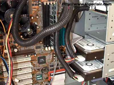
Like I said, try to get a larger loom. The one I bought was about 1/2" in diameter. I think 3/4" would have been better, so that I wouldn't have to have used as much tubing.

Once your wiring is done, stick the plastic hooks and start fitting your cables inside. You could use zip ties, and tie them to the bars inside your case, but I like these hooks because it's easy to redo the wiring later on if you need to.
If you've followed my directions, your interior should look something like this (or better, hehe)...

Ok, so I cheated a bit by using a round IDE cable, but compared to my "before" picture (which was made to look like that for demonstation purposes, really!), this came out looking a lot better. Things I'd like to have done differently would definently be the power supply cabling.
How else can this project be improved? If you're good with a dremel, you could cut holes out on the back panel to route some cabling through there. Sure, the back panel (behind the motherboard) will look like crap, but you'll likely have a side panel blocking that view. What was problematic for me, was all the extra wiring I had as a result of the various case or component fans I have installed. They run across the motherboard, and aren't really long enough to snake aroung motherboard components. I think it'd be more graceful if I was able to use fewer plastic tubing.
Ed Note: This article is a repost, with several corrections. I had problems getting things setup for additional guides using smaller cases, but we'll try to get something online in the upcoming year.
If you have any comments, be sure to hit us up in our forums.
HOME

