|
   
First Looks
The packaging is simple and low on colours, but well designed graphically in that it is quite striking. Whilst the packaging is tight, the unit is also bubble-wrapped for protection. Opening the bubble-wrap we find the main unit, an and a small bag with the screws and 2 keys. The unit is very light thanks to its aluminium construction and styled with a nice curving front.
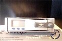  
You can't miss the predominate LCD on the front left with 3 nicely recessed blue buttons below it. To the right of the front is the "eject handle" displaying the Vantec logo across it, again recessed into the front of the unit. The sides and bottom are pretty much uneventful in things to talk about but the rear has more going on.
 
At the rear we have on the left a 40mm cooling fan, with the IDE interface sitting low and across the centre. Finally we have on the right the Molex power port making for a rear reminiscent of a CD ROM. Going back to the front again, if we pull out the eject handle we can see the 3 stage lock behind it. The internal caddy has at the front right of it a series of lines cut out, much like some sort of air guide though with the front closed it would be impossible for it to be used as such. You can also see that the LCD is part of the main unit and not attached to the front door. Pulling out the HD caddy we can see a nice dust cover drop into place much like you would find on a VCR, again displaying the Vantec logo.
  
Inside the main bay unit is naturally empty until we reach the far end. Here we have the connections for the caddy. We can also see half the rear fan. Ouch, not going to do much is it. Moving back to the caddy, inside is obviously empty until again we look at the rear portion. Here we find a very short IDE lead, a Molex power connector and three coloured jumper wires. These speak for themselves for the most part, but I'll come back to the jumper wires during installation.

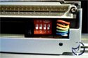
On the outside rear of the caddy we find out just how small the air guide for the fan really is. You can see it in the picture on the far left. Across the top we have the interface that connects the caddy with the bay unit and just below it the jumper dip switches. Overall the unit looks very good, is lightweight and for the most part nicely laid out.
Installation

Installation of the main bay unit is the same as any CD ROM. You put into a free 5 ¼ bay, screw into place with the supplied screws then attach the IDE and Molex power leads. One thing I should point out here is that the unit is long, longer than any of my optical drives by almost an inch. I wanted to put the unit into my lowest drive bay, but couldn't since in my case it butted up against one of the capacitors on the motherboard. If you're using this on the same channel as another hard drive you'll need to make sure your IDE leads will reach far enough between the two.

The caddy has at the top front part a little push down catch to hold the lid in place. Once this is pushed down you can slide open the lid and get ready to put your Hard Drive into place. I think the IDE and Molex power connections speak for themselves but I'll go into a bit more detail of the jumper leads. These are direct replacements for your usual jumpers, so if you had any on your drive they will have to be removed and kept somewhere safe. The explain which colours match up with which dip switch on the outside rear of the caddy so refer to that. My drive wasn't listed (a Western Digital drive) but it was simple enough to work out the settings from the tables provided. Once all the connections are made, you can insert the drive into the caddy.
You can see there really is very little room once everything is connected and the wires being as short as they are can make for a fiddly install procedure, but nothing too troublesome. Back to the dip switches, the coloured jumper wires you attached to your drive can now set the correct standard for your drive without you having to dismantle everything. Very handy in systems that are going to be using drives in multiple configurations. The 3 leads correspond to dip switches 1 through 3 with the 4th switch for setting the unit's display to either master or slave. Once the settings are done we can slide the caddy back into the main unit. The caddy slides in nice and easily, no problems there.

The door handle doesn't seem to catch too well unless you keep it in the closed position whilst shutting the door. No real problem you say, except that you then have to open the catch part way to gain access to the 3 stage lock. A minor problem and not something that would get on my nerves or anything but thought it worth a mention. Anyway, the 3 stage lock. This has 3 positions, unlocked (power off), locked (power off) and finally the position needed to use the drive, locked (power on).
Previous Page - Introduction and Specifications
Next Page - In Use and Testing
|
 Vantec EZ-Swap Mobile IDE Rack: Hard Drive caddy's are nothing new but as with more and more items from manufacturers lately, Vantec have added a host of useful extra's to give them the edge above the competition.


